How Does a Strain Gauge Work?
What is a Load Cell?
A load cell is a type of transducer that converts energy from one form to another. It is commonly used in industrial applications to measure and monitor forces. Load cells are specifically designed to convert the kinetic energy of a force, such as tension, compression, pressure, or torque, into a measurable electrical signal.
The most commonly used type of load cell in industrial applications is the strain gauge load cell. This type of load cell is accurate and cost-effective. A strain gauge load cell consists of a solid metal body or a "spring element" onto which strain gauges are securely attached. The body is typically made of materials like aluminum, alloy steel, or stainless steel, which provide durability and minimal elasticity. When a force or load is applied to the load cell, the body undergoes slight deformation. However, as long as it is not overloaded, the body always returns to its original shape. This, in turn, causes a change in the electrical resistance of the strain gauge which can then be measured as a voltage change. Since this change in output is proportional to the amount of weight applied, the weight of the object can then be determined from the change in voltage. By measuring the change in voltage output, the weight or force applied to the load cell can be accurately determined. This makes strain gauge load cells an effective tool for measuring and monitoring weights and forces in various industrial applications.
Strain Gauges
How does a load cell work?
To answer the question "How does a load cell work?" we first need to answer the question of "How does a strain gauge work?". A strain gauge is a device that measures change in electrical resistance when a force is applied. A typical strain gauge is made up of very fine wire, or foil, set up in a grid pattern in a way that produces a linear change in resistance when strain is applied along one axis. There are numerous types of strain gauges available:
- Linear strain gauges: The wire attached to the backing of the strain gauge runs parallel to the edges of the strain gauge. These are used to measure axial and bending strain.
- Shear strain gauges: The wire attached to the backing of the strain gauge is laid out in a 45º orientation to the sides of the gauge. These are used to measure shear strain.
The strain gauges are often used in tandem with more strain gauges in order to increase accuracy. One active strain gauge is referred to as a quarter-bridge, two active strain gauges are a half-bridge, and four active strain gauges are a full bridge.
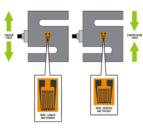
The strain gauge resistance changes differ in tension load cells vs. compression load cells. Tension force causes the strain gauge to get thinner and longer, increasing the resistance. Compression force causes the strain gauge to get thicker and shorter, decreasing resistance. The strain gauge is bonded to a thin backing (carrier), which is attached directly to the load cell enabling the strain of the load cell to be experienced by the strain gauge.

The change in resistance measured by a single strain gauge is extremely small, around 0.12Ω. A load cell’s sensitivity increases with the number of strain gauges applied. A good way of turning these small changes into something more measurable is to interconnect them as a Wheatstone bridge.
Types of Strain Gauges
Strain gauges are laid out in different orientation patterns depending on the type of force being measured. Bending strain, shear strain, axial strain, torque, and pressure are all measured using a specific layout of strain gauges. See our blog on types of strain gauges for more information.
Wheatstone Bridge
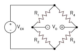
A Wheatstone bridge is a configuration of four balanced resistors with a known excitation voltage applied as shown below:
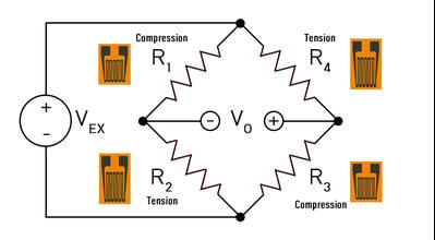
VEX is a known constant voltage and VO is measured. If all resistors are balanced, meaning R1/R2 = R4/R3 then VO is zero. If there is a change in the value of one of the resistors then VO will have a resulting change that can be measured and interpreted using Ohm’s law. Ohm’s law states that the current (I, measured in amperes) running through a conductor between two points is directly proportional to the voltage (V) across the two points. Resistance (R, measured in Ohms) is introduced as the constant in this relationship, independent of the current. Ohm’s law is expressed in the equation I = V/R.
When applied to the 4 legs of the Wheatstone bridge circuit, the resulting equation is:
| VO = | R3 | – | R2 | × VEX | ||
| R3 + R4 | R1 + R2 |
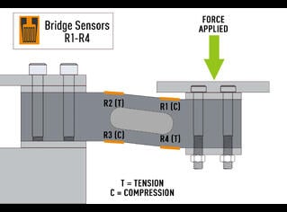
In a load cell, these resistors are replaced by strain gauges in alternating tension and compression measurements. When a force is applied to the load cell, the resistance in each strain gauge changes and VO is measured. From the resulting data, VO can be easily determined using the equation above.


How do I figure out a load cell’s sensitivity (or full-scale output/rated output) if it is not known?
In order to calculate an unknown load cell sensitivity, we will need to know the rated capacity. If you are missing the rated capacity you will not be able to perform this test. We will need to apply and record the excitation voltage used as well as the force applied.
Let’s assume we are using a 10V excitation voltage on a 5,000 lbf load cell. Let’s also apply a known load of exactly 5,000 lbf to this load cell and measure the output(mV). With a resulting measurement of 30.09mV, we can divide this value by our excitation voltage of 10V and determine this cell to have a sensitivity or full-scale rated output of 3.009 mV/V.
How do I choose the right load cell?
Factors to consider when choosing a load cell include:
Application. Will the load cell be under high stress? What level of accuracy is needed? Does my application require a wireless load cell?
Capacity. What is the maximum weight/force that will be applied to the load cell? It is recommended that the load cell capacity used exceeds the maximum force to be measured by 15%. Load cells are typically divided into classes of low, mid, and high capacity.
Size: What are the size requirements for the application? Make sure the load cell will fit into the space allowed in the application. Make sure to include space for the mounting assembly if one is required.
Shape and Type: The qualities of the force being measured help determine the type and shape of the load cell needed. For instance, there are load cells that only measure tension or compression, some measure both. Certain load cells are made to be highly responsive and work well in applications where high-speed weighing is required. Thru-hole load cells are ideal for applications in which the structure of the weighing assembly must pass through the load cell without interfering with the weighing process.
Operating environment: Load cells are manufactured to withstand varying types of environments. Load cells can be made to resist moisture and dust ingress to various levels of protection. The IP rating system is used to classify load cells according to the level they are resistant to moisture and dust. In addition to dust and moisture, some load cells are more resistant to error at extreme temperatures.
